Carbon Beauty
Composite Airframe Demonstrator
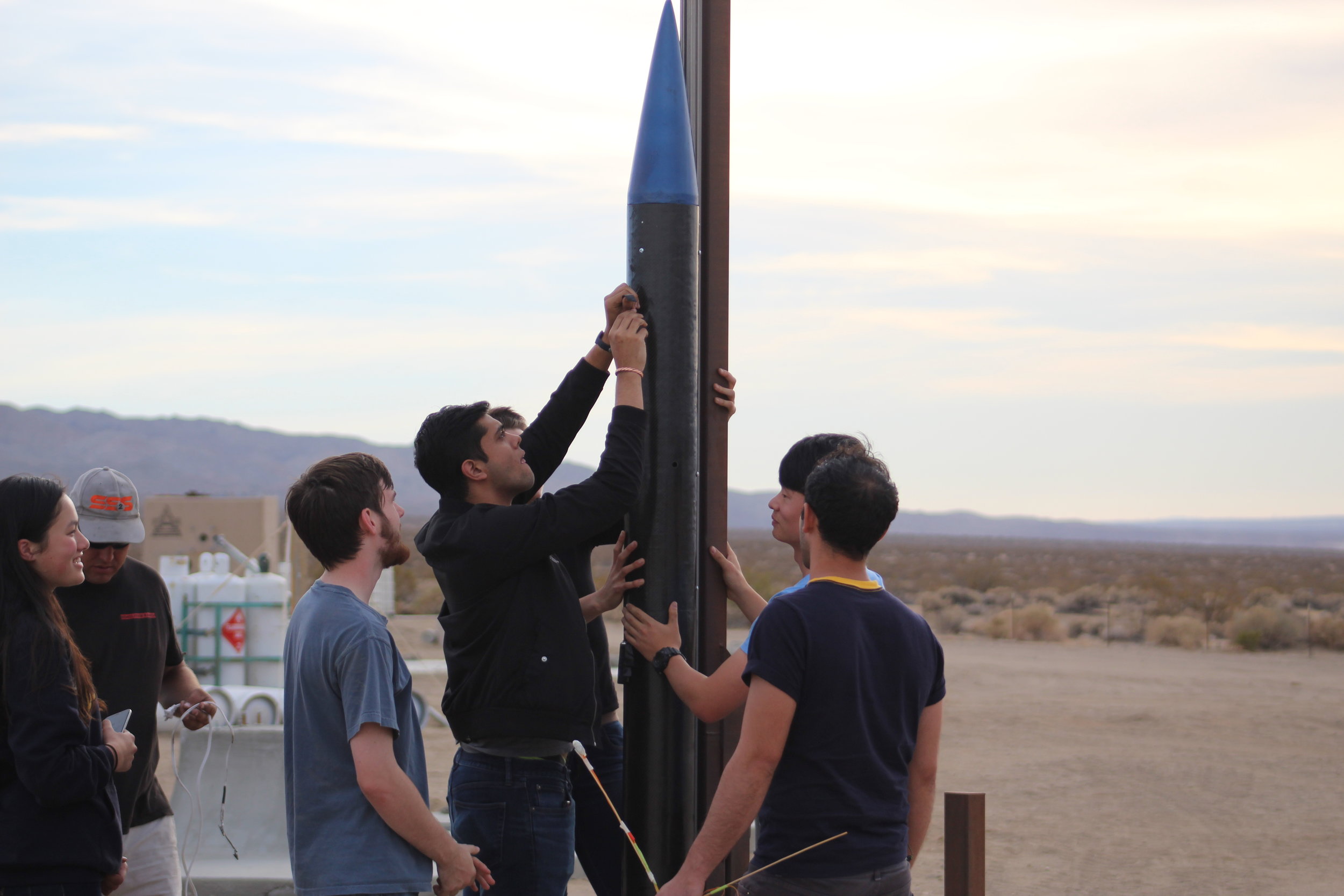
To validate and test composite fabrication techniques intended for Eureka (hypersonic space shot rocket), I led design, construction, and flight operations of the “Low Altitude Demonstrator 001 - Sparky”. The rocket used an all-composite airframe comprised of carbon fiber and fiberglass, and utilized wet layup, vacuum bagging, and cored composite construction using wood.
While only a demonstrator, Sparky set U.C. Berkeley records for both altitude (6,000 ft) and maximum velocity (Mach 0.68), supplanting previous records by CalSTAR of 5,800 ft and Mach 0.5.
ALL-COMPOSITE AIRFRAME
Sparky was built primarily using carbon fiber, fiberglass, and custom-made glass-fiber-reinforced-polymer (GFRP) in a process that I developed at Space Enterprise at Berkeley by adapting previous fiber reinforcement techniques.
The fuselage was built of 6 layers of composite, each using wet layup, in an I-Beam configuration with 2 layers of woven carbon fiber on the interior and exterior sandwiching 2 layers of woven fiberglass.
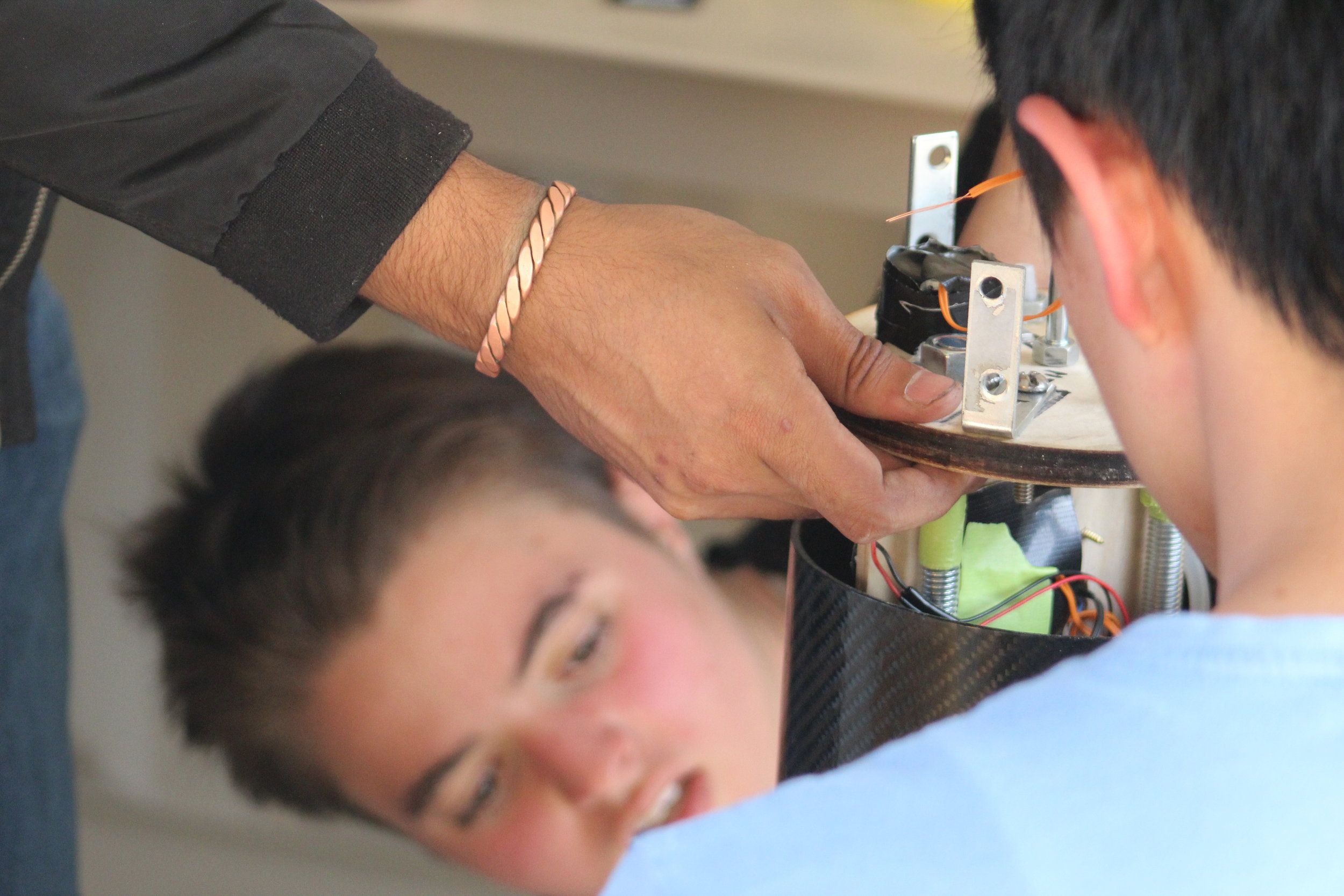
In the above image, I make an… interesting… face while arming the backup parachute deployment mechanism - a Perfectflite Stratologger hooked up to a small electric squib and black powder charge. The Stratologger is set to go off 2 seconds after apogee and serves as an insurance policy in case our custom avionics system fails.
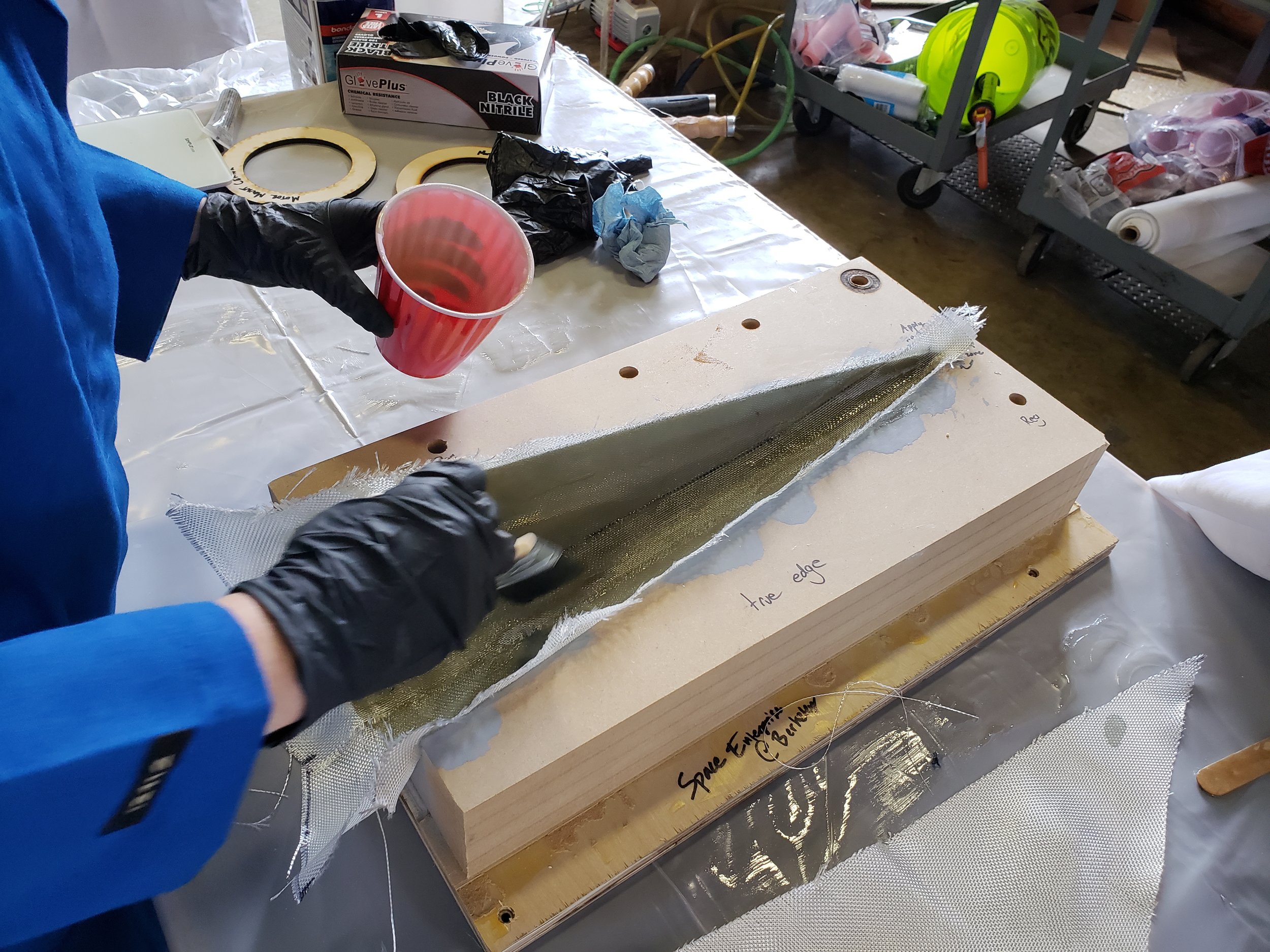
Nose Cone Layups
Using CNC-ed MDF negative molds, a we laid up fiberglass sheets to form the contour of the nose cone. While the first sheets laid down (outermost) utilized a dense fiberglass weave, we saved cost and time by utilizing fiberglass mat as a thickener and internal structural reinforcement material.
My primary responsibilities included CAD modeling of the nose cone contour, preparation of MDF molds, and providing advice and guidance to new members, who were tasked with performing the layup and operating the ShopBot CNC router.
The nose cone came together nicely, but next time, we will definitely use a more durable mold material than MDF. While it produced gorgeous parts, the finely machined surface was left ragged and damaged after parts were demolded.
Avionics Bay Woes
Design of a combined barometric/accelerometric altimeter and recovery system was assigned as project for new members, but the day before launch day, they shorted out their Raspberry Pi, backup Raspberry Pi, and barometer during testing.
In a rush, I cannibalized components and code from my Athletic Performance Tracker, coding a new flight dynamics package for Arduino and implementing multi-redundant accelerometric apogee detection systems in less than 6 hours between 11pm and 5am before catching a quick nap and beginning the drive to the Mojave.
During flight, the system performed perfectly, initiating the signal to deploy the parachute approximately half a second after apogee, as designed.

ALL SYSTEMS NOMINAL* (Exceptions may apply)
Sparky had a gorgeous flight, accelerating straight off the pad and flying perfectly straight up to an apogee of approximately 6,000 ft as recorded by the on board backup altimeter. During its flight it achieved a maximum estimated velocity of Mach 0.68 and soared high above the Mojave Desert, capturing the sunset as it flew.
Unfortunately, upon reaching apogee, the shear pins designed to cleanly separate the nose cone bent instead of snapping in shear, resulting in a leak in the parachute bay, which prevented a proper nose cone separation.
In the future, we will switch from bulk-purchased nylon shear pins to aluminum shear pins, which will have more consistent and predictable shear properties.
TIS NOTHING BUT A FLESH WOUND
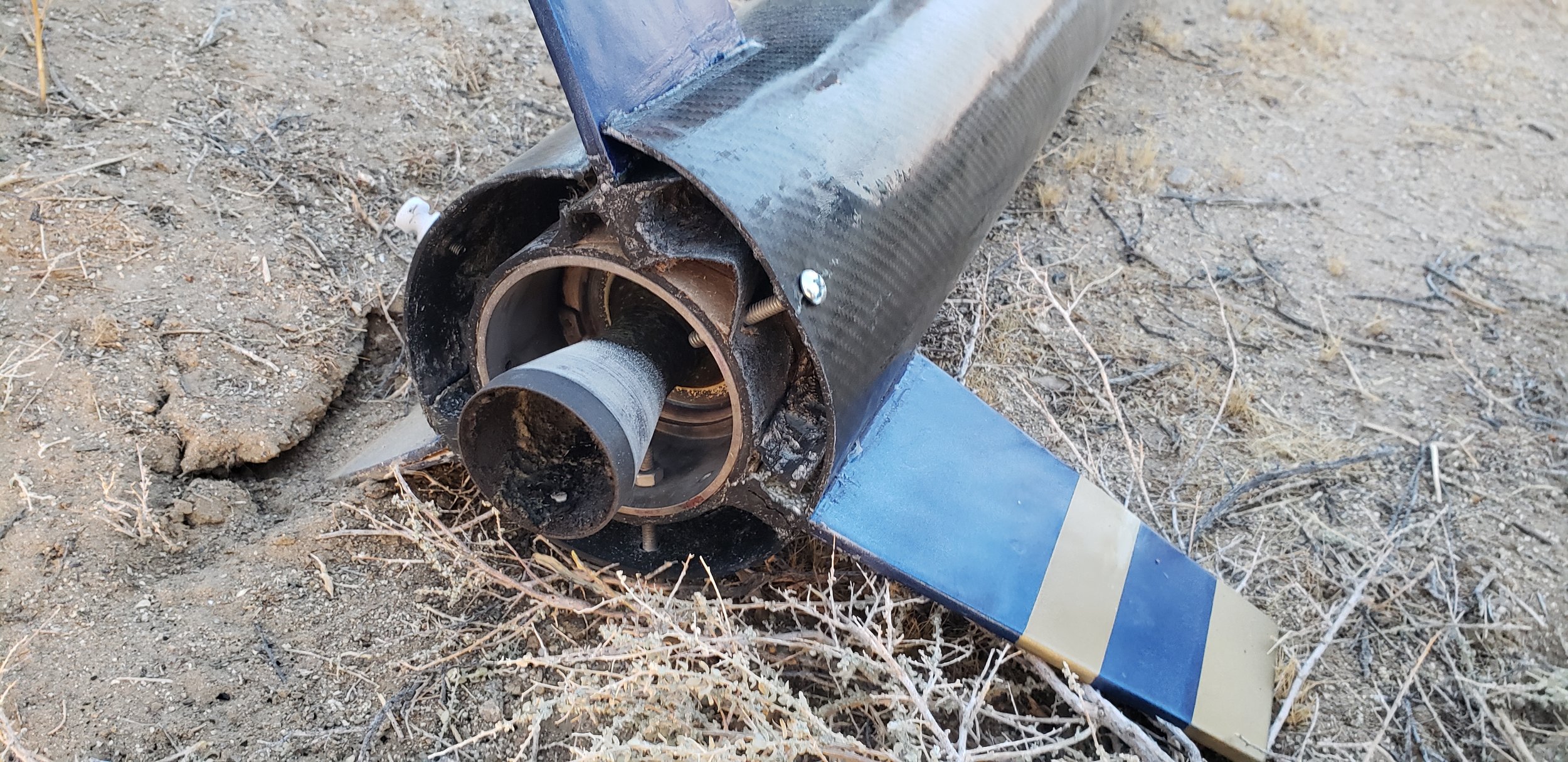
Escaping high-pressure gas from the nose cone sent the rocket into a flat spin on its way down, causing it to impact the ground flat instead of the typical “lawn dart” nose-down configuration.
In a pleasant surprise that confirmed our faith in our composite fabrication, my custom GFRP fin joints (black components between the inner and outer tube) survived the fall and remained intact (except for one which sheared away from the disposable outer motor case).
Sparky will fly again, we just have to buff out the scratches ;)
Future versions of the GFRP will incorporate more finely chopped fiber, a better method for bonding to unlike materials (something along the lines of JB Weld), and optimized overall mass by using continuous fiber sheets as external reinforcement.