Composites are like onions - they have layers
LESSONS IN COMPOSITES - PART 1/6
This post has been a long time coming…
Ever since I made the “big leap” from the CAD/simulation/data processing world to the nitty gritty of fabrication, I’ve wanted to share my insights on the benefits, detriments, and overall experience of using composite structures to build functional aerospace components.
Before I start, I want to give a huge amount of credit to Jim Jarvis, an amateur rocketeer from my home state of Texas who is anything but an amateur. This guy is a legend, and deserves the credit for creating the Jarvis Illustrated Guide to Carbon Fiber Construction, a fantastic resource that gave me the confidence to get started with building composites myself.
So here’s what this series is gonna talk about:
Multi Composite Structures
Cored Composites
Hand Layup Techniques and modifications of the Jarvis method
Nose Cone Fabrication Guide
FRP/CFRP and how to make your own for cheap
Improvements and future investigation
Multi-Composite Structures
So, you want to make a carbon fiber part, but you’ve just looked up the price of carbon fiber, and your eyes are about to pop out of your head when you ran the numbers on cost. Not to worry. Here are a few nuggets to get you started:
Yes, you do need a lot of layers.
I know, stronger than titanium, etc etc etc. HOWEVER - that’s tensile strength. Tensile strength won’t stop your part from flopping around like wet spaghetti unless that strength is coupled with stiffness. Since stiffness is proportional to the cube of thickness (for flat structures, but parallel logic applies to tubes as well), thickening your part up is the easiest and most effective way to improve stiffness, and thickness only comes from many layers of material.
If you try to thicken your part by applying extra epoxy to each layer you will quickly learn why that is not a recommended strategy
No, they do not all have to be carbon fiber
Layers in the center of a part are stressed far less than external layers, meaning you can use a weaker material as long as it won’t shear away from the layers on either side and won’t buckle or collapse under the forces placed on it.
So what does that mean for you? A world of pure imagination!
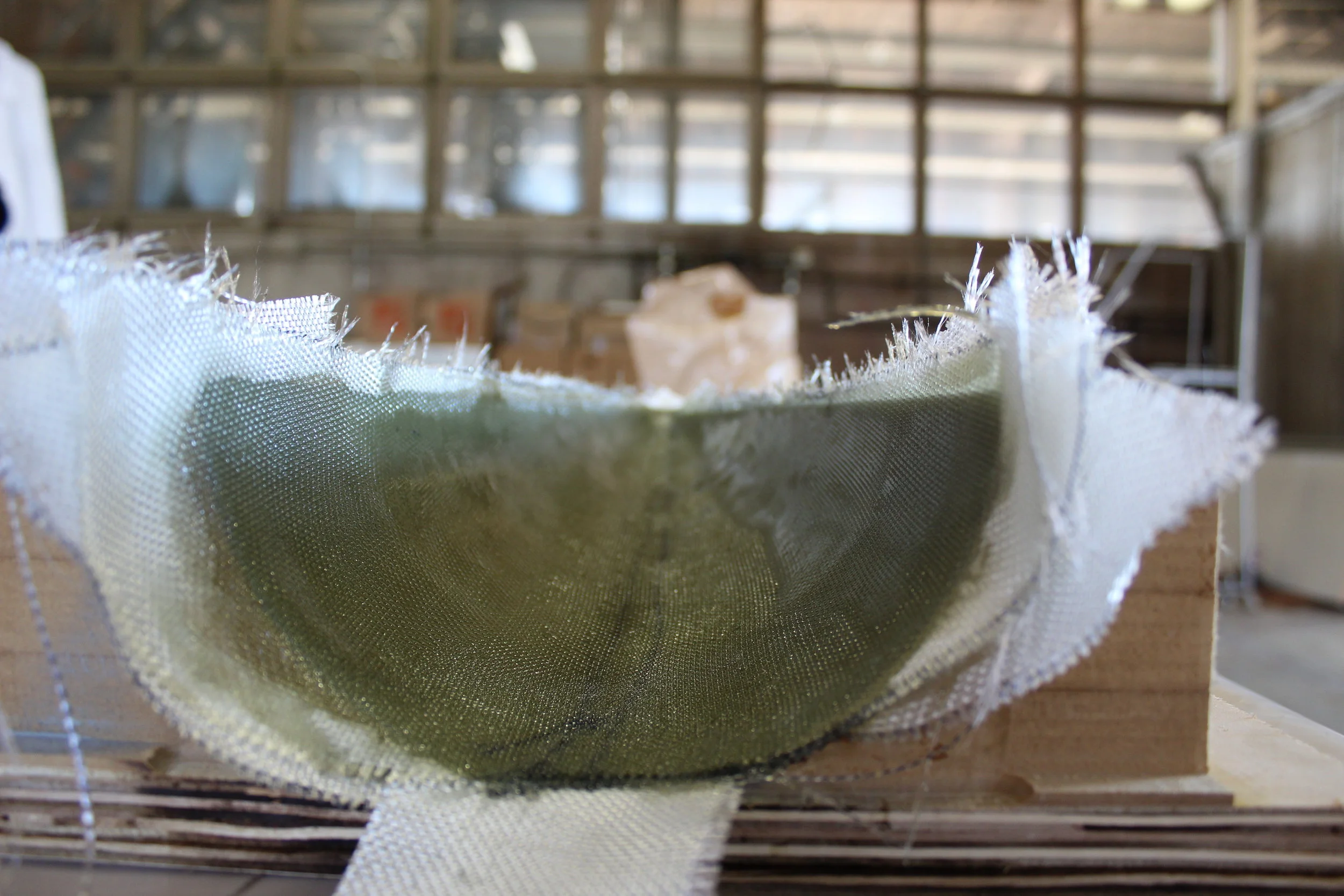
I’ll save cored composites for another time (they’re fascinating all on their own), but for today, I want to focus on multi-composite structures - ones that use more than one type of composite material - be it carbon fiber, fiberglass, kevlar, or something else.
Let’s dive right in by talking about the types of materials available to you:

Carbon Fiber
Carbon fiber is famous for its outstanding strength-to-weight, its deep black color, and its signature “glassy” look that is developed by a thin layer of resin applied to the exterior of the tube after curing.
Pictured: Airframe of LAD-Spark after finishing. You can actually see my lab coat reflected in the material!
Carbon fiber hardly needs an introduction. It’s light, strong, beautiful, and expensive.
In addition to its many favorable properties from an engineering standpoint, the black color also helps to obscure small imperfections in the surface such as ridges, wrinkles, pinholes, and similar issues.
Any layup will inevitably produce some degree of cosmetic imperfections - the question is mainly in how to prevent them from occurring as much as possible, manage the removal of them post-layup, and ensure that the strength properties of the layup are unaffected - a topic to explore in depth in Part 3 of this series.
Advantages:
1. Best possible mechanical properties
2. Readily sandable and workable post-cure (ALWAYS WEAR A RESPIRATOR)
3. Cosmetically gorgeous, very forgiving of cosmetic defects
Disadvantages:
1. Expensive
2. Faraday Cage - significantly attenuates radio transmissions
3. Failure modes are instant and catastrophic. Does not “bend before breaking”, suddenly shatters when it fails
4. Obscuring imperfections can make it harder to find them in the first place
Fiberglass
Cheaper and even more workable than carbon fiber, fiberglass is an attractive option for a rocket on a budget, parts that must be radio-transparent, or in applications where a more flexible structure is advantageous.
Pictured: Nose cone of LAD-Spark while still in its CNC-ed mold
I love fiberglass. Without breaking the bank, it offers many of the advantages of carbon fiber at a fraction of the price.
Unfortunately, it is fairly ugly cosmetically and, in the regime of yield strength, is only about half as strong as carbon fiber (it does win out on ultimate tensile strength though).
All else aside though, fiberglass is insanely cheap to make compared to carbon fiber. Not only is the material itself cheaper, the resin as a binder is 5x cheaper.
In SEB, we have had great experiences with 3M Bondo Fiberglass Resin. It’s only about $30 for a gallon (instead of nearly $150 for West Systems Epoxy). It also has the advantage of being available to buy from Home Depot, which makes it easy to restock if you run low. It also has a nice fast cure time, allowing you to finish entire layups in a single work day instead of the 24-hour turnaround on wet layup epoxy.
Advantages:
1. Best cost/performance ratio
2. Easy to work with, including sanding/painting/etc. Slightly better in this regard than carbon fiber.
3. Favorable failure modes comparable with metals - elastic deformation, yield, plastic deformation, and failure
4. Radio transparent
5. Best ultimate tensile strength
Disadvantages:
1. Not as weight-efficient as carbon fiber for a given structure
2. Cosmetically ugly unless painted. Dries an ugly off-white at best, snot-yellow at worst (see above picture)
3. Bondo Fiberglass Resin is very toxic and nasty to work with. While you should always wear appropriate PPE, the smell of Bondo is unbearable without a respirator and may disturb others working half a mile downwind (seriously, we got complaints from other clubs near us).

Kevlar / Aramid
Made famous by its use in bulletproof vests, Kevlar is an exceptionally tough impact and abrasion resistant composite material. With high cost, poor workability, and few major benefits to amateur rockets, Kevlar is not recommended for use in the context of collegiate rocketry.
Pictured: Fibreglast Kelvar Twill Weave
I have only spent a small amount of time investigating/working with Kevlar, so I’ll keep this pretty brief and to the point:
Nobody I have ever spoken to has recommended Kevlar for use in amateur high-powered rocketry.
For a moment, let’s assume that you found Kevlar to be ideal for your application. Maybe you want an impact-resistant tail, maybe you want strength like carbon fiber but you don’t want an electrical conductor, or maybe you’re especially concerned with fireproofing.
Kevlar is a nightmare to work with with traditional tools. It will dull your titanium scissors. It will chew through your carbide blades, and god help you if you want to sand it.
Oh, and the splinters it gives you are by far the worst of the three major composites.
Advantages
1. Exceptional toughness and impact resistance
2. Stronger than fiberglass in tension
3. Fireproof (do not confuse this with heat resistance - most composites will suffer serious strength degradation under temperatures above 100 C when the resin binder undergoes glass-transition and turns into Laffy Taffy)
4. Not electrically conductive
Disadvantages
1. Extremely difficult to work with. Damages tools and is near-impossible to sand
2. Expensive
3. Weak in compression
With that out of the way, let’s talk multi-composites!
What do we want? Strong, light, cheap parts that are easy to make and work with!
When do we want it? Now!
Clearly, a composite that combines favorable properties of carbon and fiberglass is desirable. This can either be done by weaving them together ($$$ and uncommon) or by layering them together in innovative ways. At SEB, we went with layering.
A few things to note with layering:
1. Use the same resin with every layer. Resin bonds most readily to itself, and a firm chemical bond between layers is essential to making a high-quality layered composite part
2. Continuous fiber wrapping is helpful but not strictly necessary. You will see improved strength, but in our experience, it is easier to get a high-quality layup when working with one layer at a time. A high-quality layup will improve strength much more readily than continuous fiber.
3. Alternating materials is not particularly efficient. Make your composite more “sandwich” than “lasagna”
So what did we make at SEB?
THE PRIMARY AIRFRAME TUBE
For the main fuselage of the rocket, we were concerned with strength in four key categories:
Compression during the boost phase of the flight (also during the ballistic phase but to a much lesser extent)
Bending during the boost and ballistic phases of the flight
Tension during parachute deployment and descent
Impact resistance on touchdown
Luckily for us, the compressive and tensile strength properties of both fiberglass and carbon fiber were more than sufficient to withstand the 1-dimensional forces of thrust from the rocket motor, drag, and parachute deployment. Of much more concern was aerodynamic bending, the magnitude of which was difficult to estimate without very good stochastic modeling of the flight path, specifically the vehicle’s angle of attack at various velocities - a task squarely outside the realm of possibility without high-quality historical wind data for the launch site (which was not available).
Using worst-case dynamic pressure loading, institutional experience that suggested that 5-layer fiberglass airframes are typically sufficient for subsonic flights, and good old fashioned “yep that seems strong enough”, we elected to use a 6-layer combined carbon fiber/fiberglass airframe structure.
To choose the most efficient combination of materials, I used I-Beam theory (maximizing the 2nd moment of inertia), and concentrated strength on the edges of the part and used the center of the part to add thickness, some strength, and more favorable failure properties.
In practice, this meant using a 2-2-2 layer structure. Starting from the outside of the tube, we used:
2 layers of 6K carbon fiber twill
2 layers of the cheapest unlabeled fiberglass weave we could find at TAP Plastics
2 layers of 6K carbon fiber twill
We also experimented with a 7-layer configuration that used 3 layers of fiberglass “mat” (unwoven fiber strands with random directions - think “bed of straw”) as the central reinforcement, but we found it difficult to conform the mat to the curved outer surface of the tube, so we abandoned mat for the primary fuselage.

Fiberglass Core Layup
We initially used a PVC pipe as a mandrel for the composite airframe, but quickly discovered that it develops a strong static electricity interaction with Mylar film, making mandrel removal near-impossible (we had to cut it apart, damaging the tube in the process).
All subsequent layups were done using disposable cardboard mailing tubes (much much easier to work with, and shockingly dimensionally accurate).
THE NOSE CONE
For the nose cone, our primary concerns were:
Strength in compression against the dynamic pressure of oncoming air
Pressure resistance against the parachute deployment charge
Radio transparency to facilitate GPS location of the rocket should it veer off course
This essentially mandated that we use fiberglass for the entire structure. To save weight and cost, we used a combination of fiberglass weave and fiberglass mat for the layup. However, the mat was applied as thickener on the inside of the nose along the seam between the two halves of the cone only (instead of between layers) due to the difficulty of getting it to conform to compound curves found in the X^3/4 shaped nose cone.

Nose Cone Layup
Applying fiberglass composite in wet layup to a CNC milled half nose cone mold. The mold was sealed with auto-body primer, covered in mold release wax, and had alignment holes to ensure a symmetric fit with its pair.
Mold release smells really good… like chap stick…
Thanks for making it to the end!
Part 2 will go through cored composites (and the construction of fins and bulkheads), and will go into slightly more detail on how to actually conduct the layups (before diving in headfirst in Part 3).
